|
RD 200J / RD 500J Joint Welder
4-Axis "Welding Robot" for
automatically joint welding of all kind rails
Highest quality welding because of none interrupted work
from bottom to top of rail.
Effectively material- and time-saving because of minimum joint space of only 12 mm.
Easiest clamp-mounting with insignificant preparation of work.
All welding parameters are memorised permanently,
only one point has to be set.
Support for your quality management system and documentation
by wireless data transfer or standard USB-port.
|
|
General Description
The standard - welding - machine RD200 /
RD500, get to be modified for joint welding.
Instead of the normal gun-holder the
rotary-support will be mounted.
From the standard-torch, the welding nozzle
will be removed and the gun handle will be
attached at mounting cone of rotary-support.
|
|
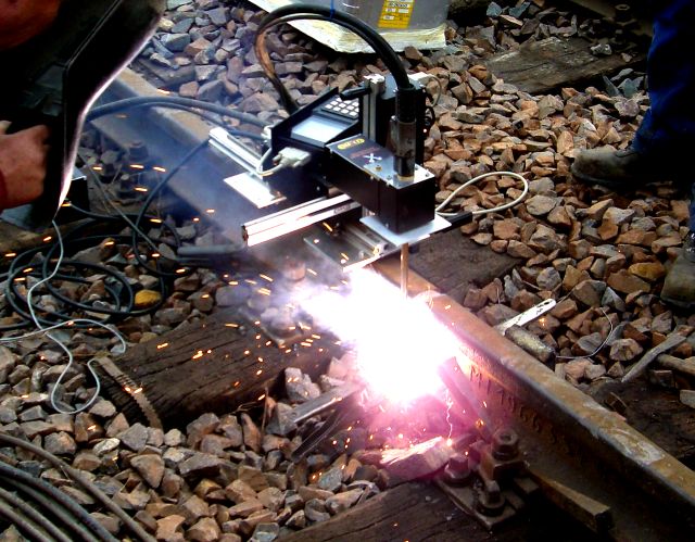
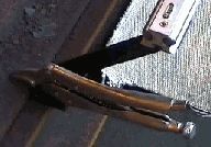
This picture shows the units building with mounting at rails bottom and application
of the normal drive rail for surface welds.
If mounting at rail head occurs, with shortened drive rail and special clamps, the distance support will be fixed more centrally. Because of grooved linear rails, the assembly is very flexible.
|
|
|
Mounting clamp at bottom ...
|
... or at rail head
|
|
|
|
Overview
1 Welding System RD200 / RD500
2 Rotary Support
3 Standard Gun
4 Welding Nozzle for manual work
5 Straight Welding Nozzle
6 Special Welding Tip
7 Backings (Copper)
|
|
|
Rail Distance to Weld Protection
The minimum ranges between rail and welding
protection should not to be reduced.
To optimise the connection for all edges, the accruing
welding dross must be able to flow off to outer.
While working and at cooling off, the dross educated
an isolation and decreases temperature differences.
Only at large outstanding material, the distance
can be decreased.
|
Automatic Welding Sequences
|
|
Grooved Rail
|
Flat Bottom Rail
|
|
After mounting of the unit and adjustment of rail type, the Zero-Point P0 can be set.
All movements will be done automatically and no further input is needed.
In special case, points P1 and/or P2 can be set additionally. P1 at different angle of cutting
and P2, very rare, at twisted mounting.
|
|
For setting of point P0, the gun will be
positioned above P0 with estimated
wire stick-out of about 35 mm.
The Rotary-Support R should be moved to the right side.
P1 can be set at mid of joint, P2 at mid of rail head.
|
|
|
|
After Switch-On, the Set-up Screen will be displayed.
- The earlier used rail number 12.
|
- Joint welding has been selected
|
|
- Working mode . The normal mode is working Behind the Unit. At not symmetrically rail heads and mounting possibilities at only one special side,
working mode can be changed to working In front of the Unit.
|
|
In front of the Unit
|
Behind the Unit
|
|
- With key 0, the unit leaves Set-up-Mode and displays the Selection Screen for rail type.
|
|
|
These are the rail parameters.
All data of every rail type are memorised permanently.
|
|
|
|
This technical drawing shows
all needed parameters for
working at all the worlds rails.
|
|
- With key 0, the unit leaves Selection Screen and shows the Working Screen.
|
|
|
Don't worry about this many different parameters,
most of them are only for your information and will be changed and adjusted very rare.
At joint welding the unit always works with pattern 5 .
All parameters are memorised in program 20.
This is a small drawing of the selected rail.
At working time, filling of rail will be indicated.
At top, name and number of rail are displayed.
|
|
This shows all standard welding parameters. All adjustments can be done by easy positioning
of the cursor and using keys +,- .
To set the Zero-Point P0, the unit should be positioned above the point and the rotary-support
should be moved to the right side. With keys 0 and + the point will be fixed.
If P1 or P2 is needed in addition, drive the unit to this point and memorise it the same way.
|
|

|
Because of rotation of the welding nozzle and a special welding tip, both sides will be reached reliable. At first layer,
a save welding bridge is created, which spares the bottom backing (copper).
|
|
|
To get a symmetrically height of layers, the rail bottom will be worked out with an even amount of
layers (2,4,6
). At constant movement with constant thickness of layers, layers with different
length will be used, from bottom to top. In this case the unit calculates the start- and end-position
of every layer.
|
To work out the slope of rail bottom, the thickness of layers at mid of rail can be calculated variable. To get the right height at mid of rail, the movement parameters between point P0 (Outside)
and point Pe (Mid) can be different.
At mid slower with short drive distance, outside faster
with large drive distance.
|
|
Previously before the unit reaches height to mount the main copper backings (Pe), the status-line
shows the message PREPARE BACKINGS !!!INPUT!!!.
If you have backings with fast fixable mounting clamps you can confirm this message with key
INPUT.
At right height (Pe), the complete display starts blinking and the backings can be mounted.
In this case the welding will be done without interruption.
If you didn't confirm the backings message, the unit will stop welding automatically at this position.
After cleaning and mounting of the side backings you can continue work by pressing button
ON.
Observe the following work.
The status-line shows positioning co-ordinates XYZR again.
After reaching of head height k, the unit stops welding.
For hard facing of last layers, welding can be stopped anytime by button GUN.
At termination with key OFF, no dwell time and no lift-off will be done.
|